Visual Inspection (AOI/manual)
Acceptance per IPC‑A‑610 class 1 (consumer products)
- Check:
wetting/fill
undersolded / oversolded
holes in solderings
flux balls
bridges
tombstoning
offset and missmatching
cold joints
polarities
missing/twisted parts
presets soldering jumper
- Additional Check:
mechanical damage
scratches on surface
scratches on matal housings
sharp edges from cutting
cutting rests
finger prints
hairs
dust
flux residues
Record in inspection log (Form C1) incl. photos for NCR
Segregate NCR units and start MRB process
Chritical shortcut positions
U5 - High Voltage Protection
The spacing between the tips does not comply with soldering guidelines and could potentially lead to short circuits. Therefore, a 100% short-circuit test must be performed by the PCB manufacturer. Any problems that arise must be resolved immediately with the supplier.
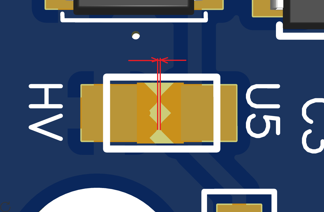
Fig.: U5 passive high voltage protection
Q3 - Hall sensor
The spacing between the pins on Q3 is very tight. If Q3 is manually populated as an option, high-quality soldering is required there. Q3 is not normally populated.
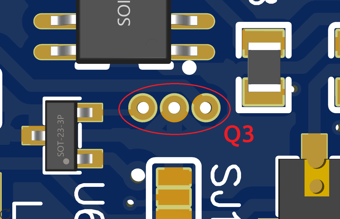
Fig.: U5 passive high voltage protection
U2 - Micro Controller
U2 must not mismatch the solder pads. All pins must be evenly and centered on the solder pads. The WiFi antenna must not protrude beyond the board.
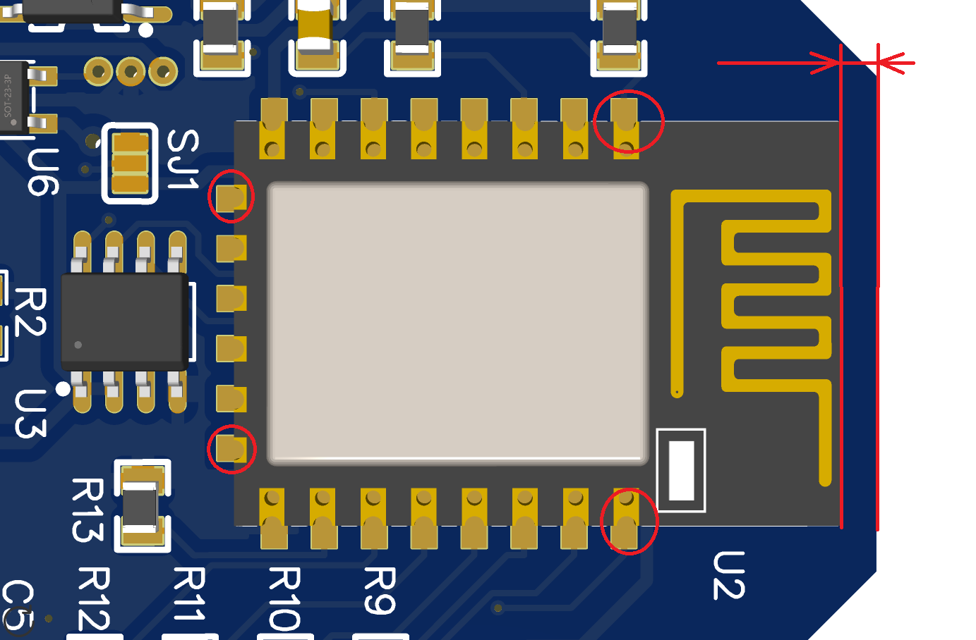
Fig.: U5 passive high voltage protection