Basic electrical test
Visual inspection passed
Short/continuity test of power rails to GND (power supplay current limiter)
Power‑on with bench PSU (current limit power source 50 mA; typically start < 20 mA)
Verify reference voltages/regulators 3,3 V +/- 0,3 V (only by problems)
- Check power supplay
12V -> max 18 mA
24V -> max 9 mA
Overvoltage > 26V -> on power supplay current limiter activ
Basic comms (UART) and programming interface check (USB login on PC)
Record results (Form D1)
Equipment
Power source 30V/1A with current limiter (setting accuracy: 0,1 V and 1 mA)
Programming adapter (Open Boat Projects)
Digital voltmeter (measuring accuracy: 1 mA)
Test Circuit
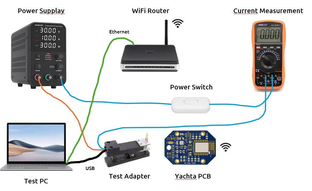
Pic.: Test circuit
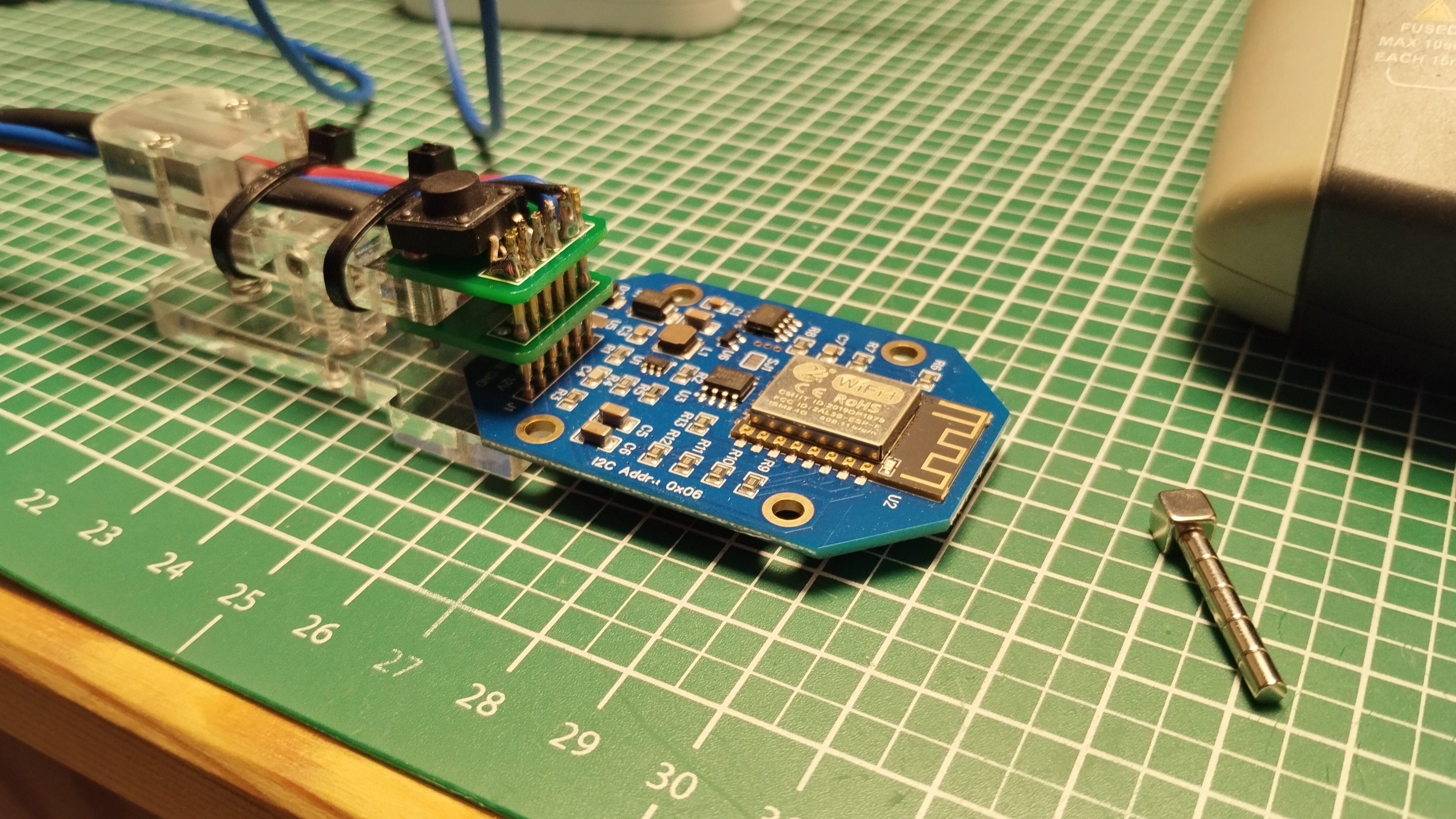
Pic.: Connected programming adapter to PCB
Test conditions
- Setting power source
50 mA currrent limit
- Digital voltmeter
Current 200 mA range
- Programming adapter
Connected to power source
Connected to digiatl voltmeter
USB connected to PC
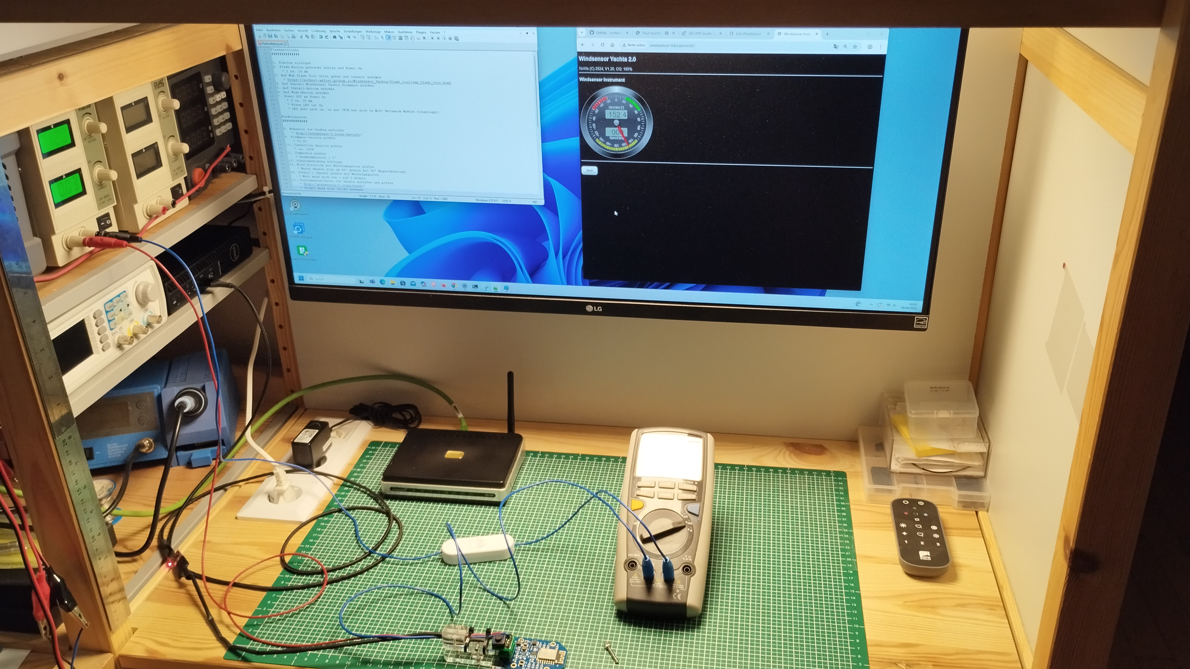
Pic.: Test place with test circuit
Test procedure
1. Set power source 12V
- 2. Connect programming adapter with PCB and switch power on (refer picture and pinning)
short led flash after powering
3. Check no-load current (max. 20 mA)
4. Set power source 24V
5. Check no-load current (max. 10 mA)
6. Set power source 30V
7. Check no-load current (current limiter activ)
Acceptance
Short led flash after powering (indicator CPU is workimg)
No power short cut
All currents in the range
Over voltage protection okay